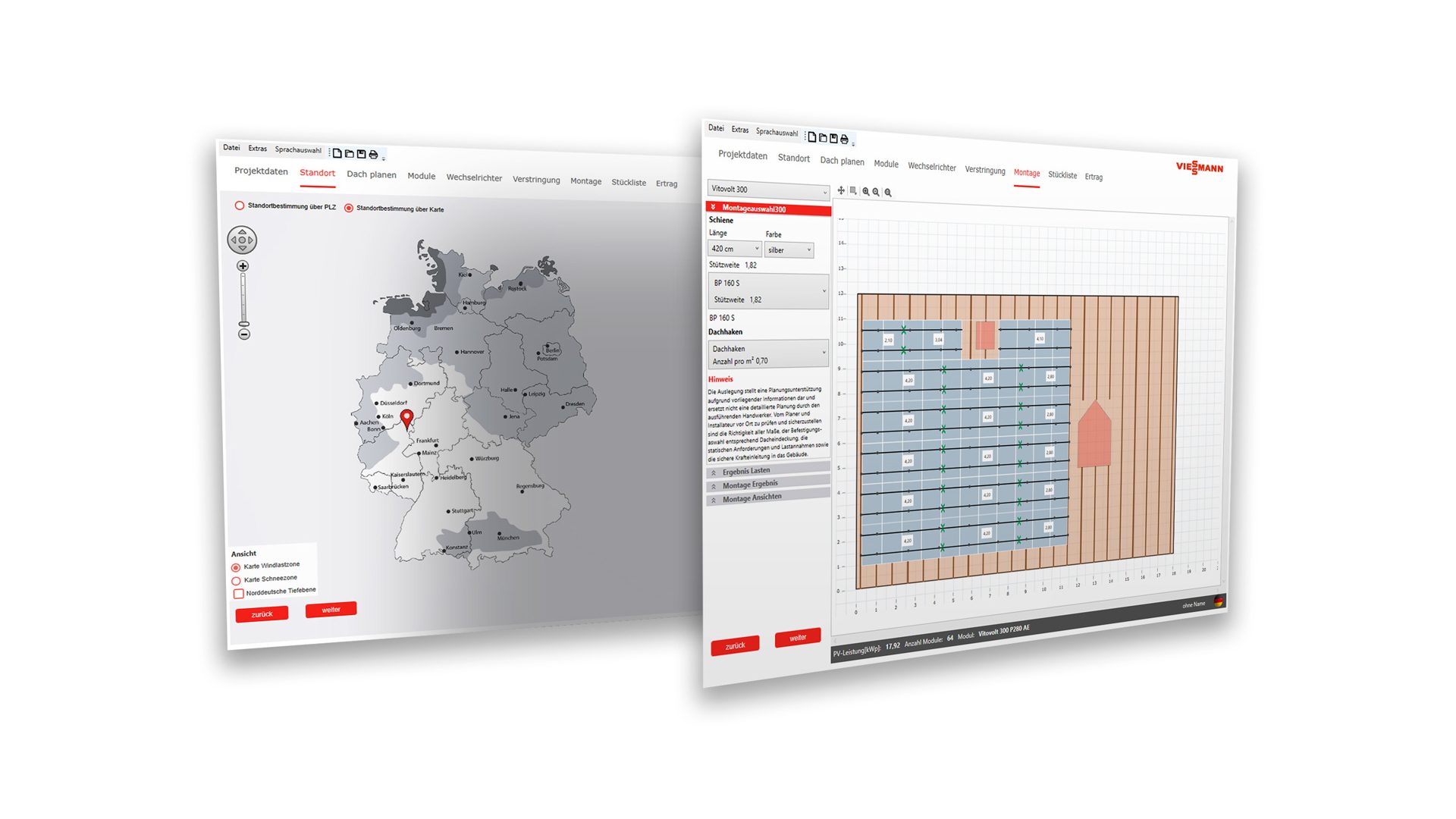
Viessmann Vitodesk 100 Solstat-PV
Professional planning program for PV systems

About the project
The traditional family company Viessmann, based in Allendorf near Frankenberg, is one of the leading international manufacturers of energy and heating systems.
Task
Development of a planning program for the PV and E systems area with which PV systems can be designed electrically and statically.
Realization
Viessmann Vitodesk 100 Solstat-PV is a sophisticated planning program for photovoltaic systems and is used by Viessmann customers and employees worldwide. The software is used in a total of 16 countries with the respective national language.
LOCATION OF THE PV SYSTEM
The user can choose the location of the PV system on a high-resolution map or by entering the postcode. The key location data for the static calculation of the assembly design are already determined via the location determination. The snow and wind loads are calculated by the selection of snow and wind load zones and the height above sea level.
Other essential parameters such as alignment, roof pitch and terrain height can be easily adjusted by the user.
ROOF PLAN
The roof planning begins with the query of the roof shape, which also defines the basic shape of the roof sketch. By entering the dimensions, the view of the roof sketch is updated immediately. The user can define any marginal areas that are an important aid when assigning modules.
The rafter spacing and the position of the individual rafters are displayed graphically. The user can determine the position of the first rafter himself.
Windows, chimney and various dormers can be dimensioned and placed by the user. The locking objects can be positioned at any time with the mouse or by entering coordinates with centimeter accuracy. When the blocking objects are placed, the roof penetrations are calculated and displayed. Rafters are divided with the penetration. Thus, it is already clear at which points there is no fastening option. The available rafters serve the possible fastening points of the assembly frame.
PV GENERATOR
The modules are selected according to the PV power. The technical detail data sheets are available as an online link.
To plan the maximum number of modules on the roof, the user uses the automatic assignment. Lock objects placed on the roof are automatically left out.
The user uses the partial assignment function for detailed planning and for special requirements of the PV system. Individual module fields can be created and placed on the roof. The modules of a module field can be arranged both horizontally and vertically. A combination of module fields with different module orientations on the roof is also possible.
The module fields are positioned here either by moving them with the mouse or by entering the coordinates (x / y values).
The number of module rows and the number of modules per row can also be edited later. Deleting individual modules as well as the entire module field enables efficient work.
INVERTER DESIGN
The user has the choice of whether to continue with the inverter design or with the assembly design after planning the PV generator.
The user can define the following parameters: design ratio, module temperature limits, unbalanced load, inverter manufacturer, filtering of individual inverter devices.
The optimal inverter solutions are determined in the automatic calculation.
The detailed result output provides information about the occupied inputs of an inverter:
- Number of strings and string length
- Current and voltage values
- Inverter ratio
Based on the automatic inverter design, the user can change the stringing, the current and voltage values are calculated and critical limit values are highlighted in color. Additional inverters can be added individually from the database and connected manually.
Automatic calculation and manual intervention can also be combined in the circuit diagram. The automatic calculation interconnects all modules on the roof with the inverter result. The user can release individual PV modules or entire module strings again and then manually assign them to a WR input. Great flexibility is provided by the option of manually interconnecting modules at critical points and having the rest calculated automatically.
ASSEMBLY
The application calculates spans and cantilevers. In the event of a cantilever error, the user can take corrective action by moving the module field or subsequently deleting modules manually.
The calculation of the pressure and suction load are calculated for the edge as well as for the normal range.
The positioning of rails and attachment points is shown graphically. The dimensioning of the rails is shown directly in the roof plan.
MATERIAL LIST
All components of the planned photovoltaic system appear in the parts list: modules, inverters, module clamps, rails, roof hooks and other fastening elements.
A distinction is made between the piece-specific material list and the order list, in which further products from the database can be added.
EARNINGS FORECAST
The planning program is rounded off by determining the expected amount.